
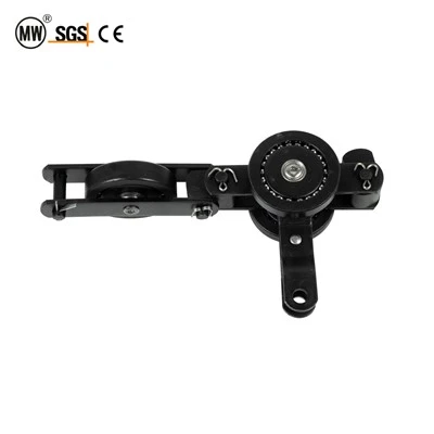
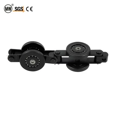
QXG200 Drive Chain
Hangzhou Ocean Industry Co., Ltd. is one of the most experienced manufacturers and suppliers of qxg200 drive chain in China. Welcome to wholesale customized qxg200 drive chain at competitive price from our factory. Good service and quality products are available.
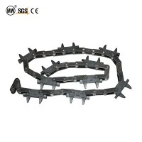
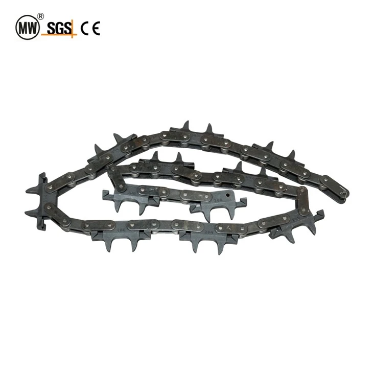
QXG200 Drive Chain - Sealed-Bearing Overhead Conveyor Transmission Chain (200mm Pitch)
The QXG200 drive chain functions as the primary traction and power-transmission element within enclosed-track overhead conveyor installations. Engineered around a 200-millimetre link pitch, this chain bridges the gap between lightweight handling systems and heavy-duty industrial lines, making it the most widely deployed pitch class in powder coating, electroplating, and general assembly applications worldwide.
Unlike lighter variants that prioritize speed over load, the QXG200 drive chain allocates more cross-sectional material to each forged link plate, raising the allowable working tension to 40 kN (standard grade) and up to 55 kN (extra-heavy grade). This headroom lets a single continuous loop carry mixed-load populations - for example, lightweight skids in drying zones and heavier fixtures in dip-tank zones - without segmenting the line or installing intermediate drives.
Every link incorporates factory-sealed rolling elements that eliminate the need for routine lubrication access, a critical advantage in contamination-sensitive environments such as food-grade processing or Class 10000 cleanroom assembly. The sealed-bearing architecture also reduces audible noise to below 62 dB(A) at nominal conveying speed, supporting compliance with workplace sound exposure limits.
As a painting line chain QXG200 conveyor chain product, it withstands sustained oven temperatures up to 250 °C (HA grade) without lubricant degradation or dimensional drift, while its drop-forged 40Cr link plates maintain HRC 38-46 hardness across the pin-hole and wheel-contact zones after millions of articulation cycles.
Drive Unit Compatibility Matrix
Selecting the correct drive engagement method is essential for transmitting torque efficiently and preventing premature chain wear. The table below maps each drive architecture to its recommended QXG200 variant and explains the engineering rationale behind the pairing.
|
Drive Architecture |
Engagement Method |
Recommended Variant |
Engineering Rationale |
|
Caterpillar (Cat) Drive |
Drive dogs grip link plates |
QXG200-S / QXG200-HH |
Distributed contact across multiple link plates reduces point loading; ideal for long straight runs with moderate accumulation |
|
Sprocket Drive |
Teeth engage pin/bushing gaps |
QXG200-S |
Precise tooth-pitch matching at 200 mm ensures smooth engagement; best for short loops with frequent start-stop cycles |
|
Friction Wheel Drive |
Rubber/polyurethane wheel bears on chain back |
QXG200-S |
Lowest impact engagement; suitable for light loads under 50 kg per point and clean-environment applications |
|
Tangential Drive |
Drive chain meshes with conveyor chain via tangential sprocket |
QXG200-HH / QXG200-HA |
Handles high cumulative tension in multi-drive loops; HA grade recommended when total loop tension exceeds 45 kN |
When specifying a painting line chain QXG200 conveyor chain installation, the caterpillar drive remains the industry default because it distributes engagement force across 4-6 link plates simultaneously, minimizing concentrated stress at any single pin joint.
Chain Configuration & Layout Planning Guide
Properly sizing a QXG200 drive chain loop requires accounting for track geometry, load distribution, thermal expansion, and wear allowance. The following planning steps ensure the installed chain operates within its design envelope from day one.
Step 1 - Measure the Track Centre-Line Length
Walk the entire conveyor path and sum the straight-section lengths plus the arc lengths of every horizontal curve and vertical bend. For horizontal curves, arc length = turning radius × bend angle (radians). For vertical bends, use the same formula with the vertical bending radius. Add 2 % to the total as a routing tolerance allowance.
Step 2 - Convert to Link Count
Divide the adjusted centre-line length by the 200 mm pitch. Round up to the next even number to ensure the chain ends meet with correct pin orientation. An odd link count forces the use of an offset link, which reduces tensile capacity by approximately 15 % and should be avoided in load-carrying loops.
Step 3 - Calculate Suspension Spacing
Fixture suspension points must be spaced at whole-number multiples of the 200 mm pitch. The formula is: Suspension Spacing = 200 + (200 × N), where N = 0, 1, 2, 3... For a typical 800 mm fixture spacing, N = 3 (200 + 600 = 800). Ensure that the chosen spacing distributes loads evenly and does not concentrate weight near drive or take-up stations.
Step 4 - Add Take-Up Allowance
Reserve 1.5 – 2 % of total chain length as take-up travel. For a 200-metre loop, this means 3 – 4 metres of adjustment range. The take-up station should be positioned at the return side, as far from the drive as possible, to maintain consistent tension across the loaded span.
Technical Specifications
Three configuration grades are available to match different load regimes. All variants share the same 200 mm pitch and attachment interface, permitting in-field upgrades without replacing the entire loop.
|
Parameter |
QXG200-S (Standard) |
QXG200-HH (Heavy Hanger) |
QXG200-HA (Extra Heavy) |
Design Note |
|
Chain Pitch (mm) |
200 |
200 |
200 |
Universal across all grades; enables mixed-grade loops |
|
Chain Mass (kg/m) |
8.5 |
9.2 |
10.1 |
Higher mass = thicker link plates; affects inertial loading |
|
Allowable Working Tension (kN) |
40 |
50 |
55 |
Rated at 20 °C, 60% RH; derate 10% per 50 °C above ambient |
|
Minimum Breaking Force (kN) |
75 |
85 |
95 |
Safety factor ≈ 1.7x working tension; batch sampling validated |
|
Single-Point Load Capacity (kg) |
80 |
100 |
120 |
Measured at 400 mm suspension spacing |
|
Suspension Interval Formula |
200+(200×N) |
200+(200×N) |
200+(200×N) |
N = integer 0-10; ensure even distribution |
|
Horizontal Wheel Ø (mm) |
90 |
100 |
110 |
Larger wheels lower contact pressure, extend bearing life |
|
Vertical Wheel Ø (mm) |
70 |
80 |
90 |
Prevents derailment at vertical curve transitions |
|
Bearing Specification |
Sealed 6204 2RS |
Sealed 6205 2RS |
Tapered Roller 30204 |
2RS = dual rubber seal; tapered handles combined loads |
|
Min. Horizontal Turn Radius (mm) |
R600 |
R650 |
R700 |
Increased for heavier grades due to wider wheelbase |
|
Min. Vertical Bend Radius (mm) |
R2500 |
R2800 |
R3200 |
Accounts for pin-bushing articulation limits |
|
Max. Operating Temperature (°C) |
≤200 |
≤220 |
≤250 |
HA uses high-temp grease rated to 300 °C intermittent |
|
Surface Treatment |
E-Coating (Black) |
E-Coating + Zinc Plating |
Hot-Dip Galvanized |
E-Coating = cathodic epoxy; 200+ hrs salt spray |
|
Nominal Chain Speed (m/min) |
0.5–15 |
0.5–12 |
0.5–10 |
Upper speed limited by bearing heat dissipation |
Values reflect standard production configurations. Custom pin diameters, alternative bearing seals, and special surface treatments available. Contact engineering for a project-specific TDS.
Tension Dynamics & Elongation Management
A properly tensioned QXG200 drive chain is invisible to operators - it runs quietly, tracks straight, and requires no intervention. Understanding the tension lifecycle helps maintenance teams predict replacement windows and avoid unplanned stoppages.
Initial Tension Setting
Set the take-up so that chain sag at the midpoint of the longest unsupported return span equals 2 – 3 % of the span length. For a 10-metre return span, this means 200 – 300 mm of visible sag. Over-tensioning accelerates bearing wear and increases drive motor current draw by 8 – 15 %; under-tensioning causes chain skip at the drive and erratic load positioning.
Wear-Induced Elongation Curve
QXG200 chains typically elongate 0.5 – 0.8 % during the first 500 hours as bearing surfaces seat and pin-bushing interfaces bed in. This "break-in" elongation is normal and absorbed by the take-up. After break-in, elongation proceeds at roughly 0.1 – 0.2 % per 1,000 operating hours under rated load.
Replacement Threshold
Replace the chain when total elongation reaches 2.5 % of nominal length. At this point, pin-hole wear compromises drive engagement geometry. For a 200-metre loop, the 2.5 % threshold corresponds to approximately 5 metres of cumulative elongation - verified by measuring a fixed 10-pitch (2,000 mm) section.
Thermal Expansion Compensation
In oven zones, a 200-metre steel chain expands by approximately 22 mm per 100 °C temperature rise. The take-up must accommodate this without bottoming out. For installations with 200 °C oven passages, reserve a minimum of 50 mm of additional take-up travel beyond the wear allowance.
Environmental Operating Envelope
|
Environmental Factor |
Operating Range |
Notes & Mitigation |
|
Ambient Temperature |
-20 °C to +250 °C (grade-dependent) |
Below -20 °C, bearing grease stiffens; specify low-temp grease. Above 250 °C, seals degrade; use HA grade. |
|
Relative Humidity |
10% – 95% (non-condensing) |
Condensation cycles drive corrosion at pin joints; upgrade to zinc-plated or galvanized treatment in tropical climates. |
|
Chemical Exposure |
Mild acid/alkali vapours acceptable |
Resistant to paint solvent vapours, electroplating mist, detergent solutions. Avoid concentrated mineral acids or chlorine gas. |
|
Particulate Loading |
Up to 5 mg/m³ airborne dust |
Sealed bearings exclude particulate; abrasive dust accelerates wheel tread wear - inspect monthly in foundry areas. |
|
Conveyor Speed |
0.5 – 15 m/min (grade-dependent) |
Below 0.5 m/min, lubricant film may not form. Above 15 m/min, derailment risk increases at curves. |
|
Duty Cycle |
Continuous (24/7) rated |
Ensure drive motor thermal protection set for S1 continuous duty, not S2 short-time. |
Selection Decision Framework
Load ≤ 80 kg/point: Select QXG200-S. Standard grade handles majority of painting line and light assembly applications. E-coating sufficient for indoor, dry environments.
Load 81–100 kg/point: Select QXG200-HH. Heavy-hanger variant adds zinc plating for enhanced corrosion resistance, recommended for electroplating lines with tank-vapour exposure.
Load 101–120 kg/point: Select QXG200-HA. Tapered roller bearings (30204) handle combined radial and thrust loads. Hot-dip galvanizing for outdoor or washdown applications.
Oven passage 200–250 °C: Mandatory HA grade. Specify high-temperature grease (lithium complex/polyurea) and fluoroelastomer seals. Confirm take-up travel accommodates thermal expansion.
Loop length > 300 m: Evaluate dual-drive configuration. Second drive at opposite end distributes tension, reduces peak chain load by 35–40%.
Frequent start-stop (>10/hr): Specify sprocket drive for precise positional control. Ensure soft-start ramp programming (3–5 sec acceleration) to limit inertial shock.
Power Transmission Mechanics
In a QXG200 overhead conveyor system, the drive chain serves three simultaneous mechanical functions: it transmits tractive force from the drive unit to every suspended load, it guides the load population along a three-dimensional path, and it maintains loop integrity through tension differentials between loaded and return spans.
The drive unit - typically a caterpillar mechanism - engages the chain by clamping drive dogs against flat faces of consecutive link plates. As the drive motor rotates, it pushes engaged links forward, and this motion propagates through pin-and-bushing articulations to the entire loop. The chain behaves like a flexible rack: rigid in tension, compliant in articulation.
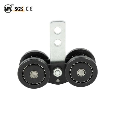
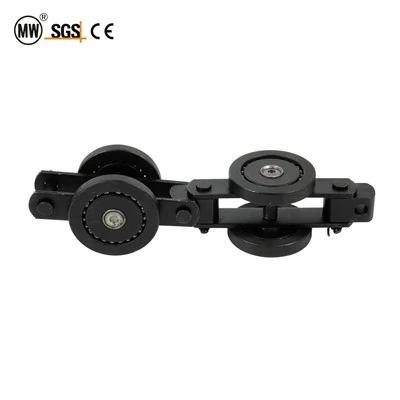
On the loaded span, the chain carries cumulative weight of all suspended fixtures plus self-weight. Horizontal wheels roll along the bottom flange of the enclosed track, converting vertical load into rolling friction (coefficient 0.002–0.003) rather than sliding friction (0.15–0.25) - the fundamental efficiency advantage of wheeled conveyor chains.
At the return span, the chain travels unloaded back to the drive. The tension differential creates a net pulling force the drive must overcome. Well-designed systems balance this differential so the drive operates at 50–70 % of rated capacity under normal load, leaving headroom for transient peaks.
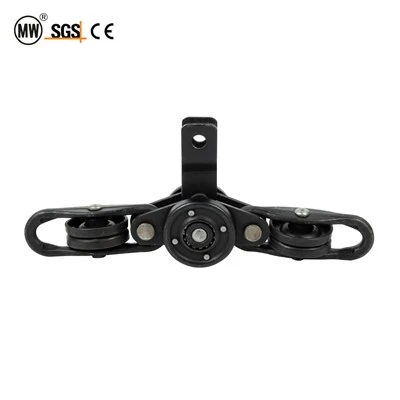
In horizontal curves, vertical wheels engage the inner sidewall to prevent lateral displacement. In vertical bends, both wheel sets share the load. Minimum radii in the technical table ensure articulation angles remain within the bearing seal's design range.
FAQ

Hot Tags: qxg200 drive chain, China qxg200 drive chain manufacturers, suppliers, factory, conveyor chain for distribution, conveyor chain for experimentation, conveyor chain for inspection services, conveyor chain for slow transport, conveyor chain for vertical conveyors, plastic conveyor chain
Previous
QXG250 Drive ChainYou Might Also Like

Send Inquiry