
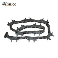
Sprocket Drive Assembly For Overhead Conveyor
Hangzhou Ocean Industry Co., Ltd. is one of the most experienced manufacturers and suppliers of sprocket drive assembly for overhead conveyor in China. Welcome to wholesale customized sprocket drive assembly for overhead conveyor at competitive price from our factory. Good service and quality products are available.
Sprocket Drive Assembly for Heavy-Duty Overhead Conveyor Systems
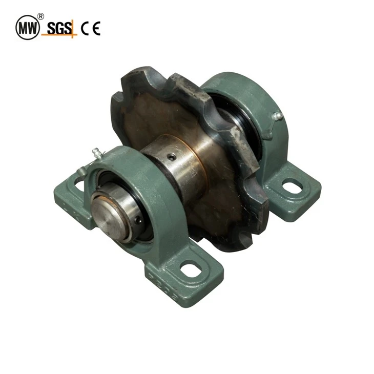
The sprocket drive assembly is the power-input node of an overhead chain conveyor. It converts the rotary output of a motor-reducer into linear chain motion, pulling the conveyor chain through horizontal track sections, vertical bends, and return loops. Unlike a bare sprocket mounted on a gearbox shaft, this assembly is supplied as a complete sub-assembly: a machined sprocket keyed to a precision shaft, supported by two sealed pillow block bearings, and ready to bolt onto the conveyor frame.
Hangzhou Ocean Industry builds these drive assemblies for powder-coating lines, paint shops, assembly systems, and material-handling conveyors that run continuously under variable load. The sprocket teeth are cut to match the pitch of the target chain, while the bearing centers and shaft diameter are selected to keep deflection within tolerance even when the chain tension peaks during startup or heavy loading.
Operating Environment & Suitability
Drive assemblies are normally installed at the head or tail of the conveyor circuit, either as the motorized drive station or as an idler/take-up station. The cast-iron housings and grease-sealed bearings are designed for indoor industrial environments with ambient temperatures between -20°C and +80°C. For oven exit zones or curing-line drives where radiant heat is present, high-temperature seals and synthetic grease can be specified to extend bearing life.
The standard finish is machine-grey or green alkyd enamel on the housings, with a thin oil film on exposed steel surfaces. For wet or chemically aggressive installations such as phosphate pretreatment lines, Dacromet or zinc-plated coatings are available on the shaft and sprocket to prevent rust migration into the bearing seals.
Engineering Selection & Configuration Guidance
Specifying the correct sprocket drive assembly starts with the chain parameters and the required line speed, then works back to the sprocket geometry and bearing loads:
Match the chain pitch exactly. X348, X458, X678, XT160 and QXG-series chains each require a sprocket with the corresponding pitch and tooth profile. A mismatched pitch will accelerate tooth wear and cause chain jumping.
Choose tooth count for speed and wrap. Drive sprockets usually have 8–13 teeth. Fewer teeth increase pulling torque but raise chordal action; more teeth run smoother but require a larger envelope.
Size the shaft for deflection, not just torque. The shaft span between pillow block bearings should keep total deflection below 0.05% of the span length under maximum chain tension.
Select bearing load rating with a safety factor. Use a dynamic load rating at least 1.5 times the calculated radial load from chain pull, especially in indexing or start-stop applications.
If you are replacing an existing drive, send the old sprocket diameter, bore size, shaft center distance, and chain model. We can reverse-engineer a drop-in replacement or upgrade the bearing rating while keeping the same mounting footprint.
Component Breakdown
|
Component |
Material / Specification |
Function |
|
Sprocket |
45# steel or 40Cr, teeth induction hardened HRC 45–50 |
Engages chain rollers/pins and converts torque to chain pull |
|
Shaft |
40Cr, quenched and tempered, ground finish |
Transmits torque from reducer to sprocket, resists bending |
|
Pillow block bearings |
Cast iron housing, UC insert bearing, double-lip seals |
Supports shaft, absorbs radial load, allows easy mounting |
|
Key & set screws |
45# steel, black oxide finish |
Locks sprocket to shaft, prevents fretting and backlash |
|
Housing finish |
Green alkyd enamel or grey hammer tone paint |
Corrosion protection and visual identification |
Technical Specifications
The table below lists representative sizes. Because drive assemblies are matched to the conveyor chain and reducer interface, custom dimensions are our standard offering.
|
Parameter |
Value / Range |
Notes |
|
Applicable chain pitch |
100 / 150 / 160 / 200 / 250 / 300 mm |
Match to X348, X458, X678, XT160, QXG series |
|
Sprocket teeth |
8 – 13 teeth (drive); 6 – 10 teeth (idler) |
Other tooth counts on request |
|
Shaft diameter |
30 mm – 60 mm |
Sized for torque and deflection limits |
|
Bearing center distance |
180 mm – 400 mm |
Depends on sprocket diameter and load |
|
Torque capacity |
500 – 3,000 Nm |
Service factor ≥ 1.5 recommended |
|
Max line speed |
0 – 20 m/min |
Higher speeds with balanced sprocket |
|
Operating temperature |
-20°C ~ +80°C (standard seals) |
High-temp seals to +150°C optional |
|
Lubrication |
Grease nipple on each bearing housing |
Lithium-based EP grease recommended |
|
Mounting |
Two-bolt pillow block base |
Slotted holes for chain tension adjustment |
Installation & Maintenance Precautions
Mount the assembly on a flat, rigid steel frame. Flexible supports will allow the sprocket to move under load and accelerate chain wear.
Align the shaft axis parallel to the conveyor track within 0.1 mm per 100 mm length. Misalignment causes side loading on the chain and uneven tooth wear.
Leave the bearing mounting bolts slightly loose, run the conveyor under no-load for one full loop, then tighten evenly. This lets the chain center the sprocket naturally.
Set initial chain sag to 1.5%–2% of the center distance on the return side. Too tight increases bearing and chain load; too loose causes surging.
Check the sprocket tooth engagement across the full width. The chain should sit squarely on the teeth without rubbing the side plates.
Do not apply belt or chain tension until the reducer has been aligned to the drive shaft coupling. Coupling misalignment is a common cause of bearing failure.
FAQ

Hot Tags: sprocket drive assembly for overhead conveyor, China sprocket drive assembly for overhead conveyor manufacturers, suppliers, factory, 5T Caterpillar Drive Unit, automotive drive unit, Five Tons Series Drive Unit, heavy-duty drive unit, quality drive unit, stepper drive unit
Previous
No InformationYou Might Also Like


Send Inquiry