


Integral Shaft Guide Roller For Closed Track Conveyor
Hangzhou Ocean Industry Co., Ltd. is one of the most experienced manufacturers and suppliers of integral shaft guide roller for closed track conveyor in China. Welcome to wholesale customized integral shaft guide roller for closed track conveyor at competitive price from our factory. Good service and quality products are available.
Integral Shaft Guide Roller for Closed Track Conveyor
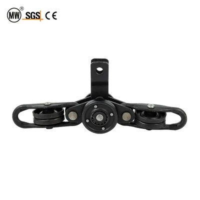
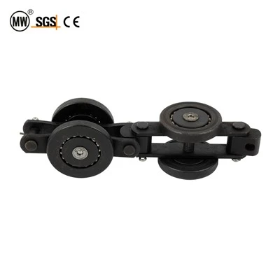
Every QXG enclosed-track chain link carries two families of wheels: tread wheels that support the payload vertically, and guide rollers that steer the chain through every direction change - horizontal bends, vertical dips, and compound spiral transitions. The guide roller's rotational axis is parallel to the chain pitch direction, perpendicular to the tread wheel axis. It contacts the inner web of the closed-track box section at curves, converting the chain's linear momentum into centripetal steering force. Without the guide roller, the chain would fly off the track at the first 90° bend.
The integral shaft guide roller solves a specific failure mode that plagues pressed-in axle designs. In a pressed-in axle configuration, the axle is a separate cylindrical pin that is force-fitted into the roller body bore. Under repeated lateral shock loads at curve entries (where the guide roller absorbs 60–80% of the chain's centripetal force), the press-fit decays - the axle gradually loosens, develops axial play of 0.5–2.0 mm, and eventually ejects from the roller body during a vertical curve ascent. The chain derails. The line stops. The operator scrambles to find the ejected axle on a 200°C oven floor. The integral shaft design eliminates this scenario entirely: the axle is forged as a monolithic extension of the roller body. There is no press-fit interface, no interference-fit decay curve, no separate component to eject. The axle and roller body are one continuous piece of drop-forged 45# high-carbon steel - the same material used for trolley brackets, chosen for its combination of forgeability, core toughness, and surface-hardening response.
Pressed-In Axle vs. Integral Shaft – The Ejection Failure
In pressed-in axle guide rollers, the axle-to-body connection relies entirely on radial friction from an interference fit (typically 0.02–0.04 mm). This friction is sufficient for static loads, but decays rapidly under the dynamic environment of an overhead conveyor:
• Curve entry shock: each horizontal or vertical bend generates a lateral impact of 2.0–3.5× the static centripetal load, transmitted directly to the axle-to-body press-fit interface.
• Thermal cycling: oven zones raise the roller body to 180–200°C. The bore expands radially (thermal expansion coefficient of steel: 12×10⁻⁶/°C). The press-fit interference of 0.02 mm is consumed by ΔD = 12×10⁻⁶ × 35mm × 200°C = 0.084 mm - the bore expands 4.2× more than the original interference. At oven temperature, the press-fit becomes a clearance fit. The axle is loose.
• Gravity assist on vertical ascents: when the chain climbs a vertical bend, gravity pulls the axle downward. Combined with the thermal clearance, the axle can eject 0.5–2.0 mm per cycle. After 500–1 000 oven-pass cycles, the axle has walked out of the roller body completely.
• Post-ejection consequence chain: axle ejection → guide roller → chain loses steering at curve → chain contacts track wall instead of web → track wall deformation → chain derailment → full line shutdown. Average recovery time: 2–4 hours. Average production loss: $2 000–$8 000 per event.
The integral shaft design eliminates every mechanism in this chain: no press-fit interface to decay, no thermal expansion gap to open, no separate component for gravity to pull. The forged one-piece axle is part of the roller body's metallurgical structure - it cannot loosen, walk, or eject under any combination of shock, heat, and gravity.
Pressed-In Axle vs. Integral Shaft – 8-Point Comparison
|
Feature |
Pressed-In Axle |
Integral Shaft |
Conveyor Impact |
|
Axle-to-body connection |
Interference fit (friction only) |
Forged monolithic (metallurgical bond) |
No interface to decay - zero loosening risk |
|
Thermal stability at 200°C |
Bore expands 4.2× beyond interference → clearance fit |
Shaft expands with body at same rate → bond maintained |
Oven-zone reliability from 500 h to 50 000 h |
|
Axle ejection risk |
0.5–2.0 mm walk per oven cycle; full ejection at 500–1 000 cycles |
Impossible - axle is part of body |
Zero derailment events from guide roller axle loss |
|
Concentricity over life |
Decays as press-fit relaxes: 0.03 mm → 0.10 mm at 5 000 h |
Locked at ≤ 0.03 mm through 50 000 h |
Tread contact remains stable; no track wall scoring |
|
Vertical curve safety |
Gravity pulls loose axle downward → progressive ejection |
Gravity acts on unified mass → no differential movement |
Chain stays steered through every vertical ascent |
|
Post-failure recovery |
2–4 h downtime per ejection event; $2 000–$8 000 loss |
No ejection events → no recovery needed |
Annual downtime reduction: 8–16 h eliminated |
|
Maintenance inspection |
Weekly: check axle protrusion with depth gauge |
Quarterly: visual tread wear check only |
Inspection labor reduced 75% |
|
Cost delta per roller |
Baseline |
+$0.80–$1.50 (forging + CNC vs. pin insertion) |
ROI: $1.50 extra saves $8 000+ per ejection event avoided |
Technical Specifications
|
Parameter |
QXG150 / 200 / 206 |
QXG240 / 250 / 300 |
|
Guide roller outer diameter (tread) |
Φ28 mm (QXG150) / Φ32 mm (QXG200/206) |
Φ34 mm (QXG240) / Φ36 mm (QXG250) / Φ40 mm (QXG300) |
|
Tread width |
12 mm |
14 mm |
|
Tread profile |
Crowned convex - reduced track-web contact stress at curve entry |
Crowned convex - wider contact patch for heavier chain loads |
|
Integral shaft diameter |
Φ12.0 mm (QXG150) / Φ14.0 mm (QXG200/206) |
Φ15.0 mm (QXG240/250) / Φ17.0 mm (QXG300) |
|
Integral shaft length (exposed beyond roller) |
22 mm (QXG150) / 26 mm (QXG200/206) |
28 mm (QXG240/250) / 32 mm (QXG300) |
|
Shaft-to-tread concentricity |
≤ 0.03 mm (CNC-turned from single forging) |
≤ 0.03 mm |
|
Shaft surface finish (Ra) |
≤ 0.8 μm (bearing inner race contact zone) |
≤ 0.8 μm |
|
Shaft hardness (induction hardened) |
HRC 55–60, depth 1.5–2.0 mm (inner race contact zone) |
HRC 55–60 |
|
Tread hardness (induction hardened) |
HRC 58–62, depth 2.0–3.0 mm |
HRC 58–62 |
|
Core hardness (tempered) |
HRC 28–35 (45# forged blank, core toughness) |
HRC 28–35 |
|
Material (roller body + shaft) |
45# high-carbon steel, drop-forged blank, CNC-turned |
45# high-carbon steel, drop-forged |
|
Bearing type |
6201-2RS deep-groove ball (Φ28mm roller) / 6202-2RS (Φ32mm) |
6202-2RS (Φ34/36mm) / 6203-2RS (Φ40mm) |
|
Bearing bore (press-fit into roller body) |
Φ26 mm (6201 seat) / Φ35 mm (6202 seat), interference 0.01–0.015 mm |
Φ35 mm (6202) / Φ40 mm (6203) |
|
Seal system |
6201/6202-2RS double rubber seal + dual labyrinth metal shield |
6202/6203-2RS + dual labyrinth metal shield |
|
Oven-zone seal option |
Dual labyrinth metal only (no rubber) - rated 200°C continuous |
Dual labyrinth metal only - 200°C rated |
|
Swaging method |
Rotary swaging - integral shaft riveted to chain link plate |
Rotary swaging to link plate |
|
Swage collar coverage |
≥ 80% of shaft end face area |
≥ 80% |
|
Dynamic load rating (lateral, per roller) |
1 200 N (6201) / 2 800 N (6202 sealed) |
2 800 N (6202) / 4 800 N (6203) |
|
Static load rating (lateral) |
800 N (6201) / 1 900 N (6202) |
1 900 N / 3 200 N (6203) |
|
Max chain speed |
25 m/min (sealed) / 30 m/min (open full complement) |
25 m/min / 30 m/min |
|
Max continuous temperature |
200°C (metal seal + polyurea grease) |
200°C |
|
Roller weight (approx.) |
0.12 kg (QXG150) / 0.18 kg (QXG200) |
0.22 kg (QXG250) / 0.30 kg (QXG300) |
|
Surface treatment |
Phosphated + oiled (standard) / Zinc-plated (optional) |
Phosphated + oiled / Zinc-plated |
|
Orientation on chain |
Axis parallel to pitch direction; perpendicular to tread wheel axis |
Same orientation across all QXG models |
QXG Chain Link Wheel System – Tread vs. Guide Role Architecture
Each QXG chain link carries a four-wheel system that divides the conveyor's mechanical demands between two specialized wheel families:
|
Attribute |
Tread Wheel (Walking Wheel) |
Guide Roller (Steering Roller) |
Why Two Families? |
|
Axis direction |
Perpendicular to chain pitch (vertical plane) |
Parallel to chain pitch (horizontal plane) |
Tread carries vertical load; guide steers lateral direction |
|
Primary function |
Payload support - carries pendant weight on I-beam flange |
Direction steering - contacts track web at curves |
Division of labor: vertical vs. lateral |
|
Load type |
Static radial (pendant weight) + dynamic radial (curve entry) |
Lateral centripetal (curve steering) + lateral shock (curve entry impact) |
Different load vector = different optimal geometry |
|
Diameter |
52–78 mm (large for load distribution) |
28–40 mm (small for tight track web clearance) |
Guide must fit within enclosed track box section width |
|
Bore architecture |
Counterbore step bore (bearing seat + axle guide) |
Integral shaft (forged one-piece axle) |
Tread needs removable axle for bracket swaging; guide needs permanent shaft for link plate swaging |
|
Bearing size |
6202 / 6203 (larger for higher radial load) |
6201 / 6202 / 6203 (scaled to roller diameter) |
Guide roller carries less static load but higher lateral shock |
|
Failure mode priority |
Bearing creep (counterbore shelf solves this) |
Axle ejection (integral shaft solves this) |
Each family has its critical failure - each solved by its specific bore/shaft architecture |
|
Quantity per chain pitch |
2 (one per chain plate side) |
2 (one per chain plate side) |
4 wheels total per pitch = complete support + steering system |
Application Scenarios
1. Automotive Multi-Radius Powder Coating (QXG250 / 300)
Large automotive components (brackets, subframes, 15–50 kg) traverse complex multi-radius circuits with 4–8 horizontal bends (R400–R1200 mm) and 2–4 vertical dips. Each bend generates 2.0–3.5× lateral shock on the guide roller. Integral shaft prevents axle ejection during 200°C cure oven passage following each curve. Typical: 1 500-3 000 guide rollers per line, 24/7, 50 000 h rated life.
2. Appliance E-Coating Vertical Immersion Lines (QXG200 / 206)
Refrigerator panels and washer drums pass through vertical immersion tanks (dips of 1.5–2.5 m depth) requiring steep vertical ascents at R500–R600 mm. The integral shaft's gravity-proof design is critical: no pressed-in axle can survive the repeated vertical climbs in a 200°C bake oven following the dip. Guide roller size Φ32 mm (6202 bearing) provides adequate lateral force capacity for 10–25 kg pendants at 8–15 m/min.
3. Furniture Hardware Compact Layout Lines (QXG150)
Small furniture brackets and hinges (5–8 kg) on compact factory layouts with tight R400 mm return bends. The Φ28 mm guide roller with integral Φ12 mm shaft fits within the QXG150 track's narrow box section (62×68 mm), steering the chain through tight curves without track-web contact stress. Crowned tread profile protects the thin enclosed-track web at these tight radii.
4. Food Processing Stainless Conveyor (Custom SS Shaft)
304SS integral shaft guide roller for meat processing and bakery conveyor lines. Food-grade polyurea grease (NSF H1), dual labyrinth metal seal only (no rubber, daily 80°C sanitize wash compatible). The 304SS integral shaft cannot corrode at the shaft-to-body interface (there is no interface - it's one piece), eliminating the galvanic corrosion failure that pressed-in axle designs suffer in wash-down environments.
Engineering Selection Guide
Step 1: Match Guide Roller to Chain Model
|
Chain Model |
Guide Roller Specification |
|
QXG150 (pitch 150 mm, 8 kg pendant) |
Φ28 mm tread / Φ12 mm integral shaft / 6201 bearing |
|
QXG200 (pitch 200 mm, 15 kg pendant) |
Φ32 mm tread / Φ14 mm integral shaft / 6202 bearing |
|
QXG206 (pitch 206 mm, 15 kg pendant) |
Φ32 mm tread / Φ14 mm shaft / 6202 bearing |
|
QXG240 (pitch 240 mm, 20 kg pendant) |
Φ34 mm tread / Φ15 mm shaft / 6202 bearing |
|
QXG250 (pitch 250 mm, 25 kg pendant) |
Φ36 mm tread / Φ15 mm shaft / 6202 bearing |
|
QXG300 (pitch 300 mm, 50 kg pendant) |
Φ40 mm tread / Φ17 mm shaft / 6203 bearing |
Step 2: Choose Bearing + Seal Configuration
|
Configuration |
Best For |
|
6201/6202-2RS sealed + dual labyrinth |
General painting, plating, assembly - self-contained lube, 0.5–25 m/min, −10–200°C |
|
Metal labyrinth only (no rubber) - oven variant |
Continuous 200°C oven zones - no rubber hardening, with polyurea high-temp grease |
|
Full complement open type + auto-spray lube |
Heavy lateral load (>80% rated) or high speed (>25 m/min) with external lube system |
Step 3: Select Surface Treatment
|
Treatment |
Best For |
|
Phosphated + oiled (standard) |
Indoor painting / powder coating - best value |
|
Zinc-plated (Zn 8–12 μm) |
Wet environments: wash, rinse, plating - 200–400 h salt spray |
|
304SS solid stainless |
Food-grade, pharmaceutical, extreme chemical - daily sanitize |
Step 4: Verify Vertical Curve Safety
|
Check Point |
Requirement |
|
Vertical ascent radius |
≥ R500 mm (integral shaft: gravity-safe at any angle) |
|
Number of oven cycles per day |
Integral shaft: no limit (no press-fit decay) |
|
Pendant weight on vertical climb |
≤ rated static lateral load of guide roller bearing |
FAQ

Hot Tags: integral shaft guide roller for closed track conveyor, China integral shaft guide roller for closed track conveyor manufacturers, suppliers, factory, conveyor chain for asynchronous operation, conveyor chain for design services, conveyor chain for efficient design, conveyor chain for safety regulations, conveyor chain for standardization, conveyor chain tensioners
Previous
No InformationYou Might Also Like


Send Inquiry