


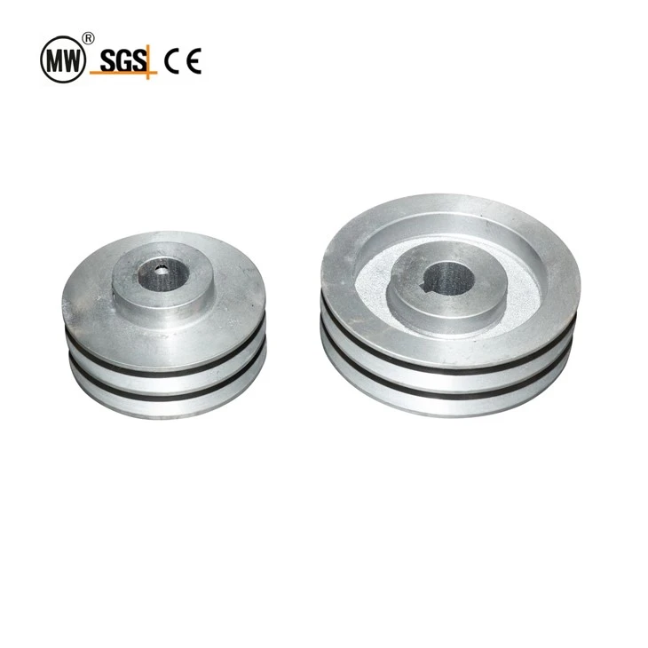
Two Groove Cast Iron V Belt Pulley For Conveyor Motor
Hangzhou Ocean Industry Co., Ltd. is one of the most experienced manufacturers and suppliers of two groove cast iron v belt pulley for conveyor motor in China. Welcome to wholesale customized two groove cast iron v belt pulley for conveyor motor at competitive price from our factory. Good service and quality products are available.
Dual Groove SPZ/SPA/SPB Taper Bush Sheave for QXG Overhead Conveyor Drive Systems
Every overhead conveyor line has a hidden mathematical equation sitting between the electric motor and the drive unit: the pulley ratio. This ratio determines whether your chain crawls at 0.5 m/min or races at 15 m/min - and the component that enforces it is the V belt pulley mounted on the motor shaft. When this pulley is wrong, the entire coating line delivers the wrong film thickness.
The two groove cast iron V belt pulley is the primary speed-reduction interface in QXG-series enclosed-track overhead conveyor systems. It mounts directly onto the motor output shaft via a taper bush hub and transmits torque to the drive unit input sheave through a matched pair of V belts. The dual-groove design provides twice the friction surface area of a single-groove pulley, enabling reliable torque transmission up to 5.5 kW for SPZ/SPA profiles and 15 kW for SPB without belt slip - a critical requirement for paint and powder coating lines where any speed fluctuation results in uneven film thickness and rejected parts.
Manufactured from HT250 (GG25) gray cast iron with fully machined groove profiles to ISO 4183 dimensional tolerances, each pulley undergoes dynamic balancing to G6.3 grade per ISO 21940-11 before leaving the factory. The taper bush mounting system (SPZ: 1008-1610, SPA: 1108-2517, SPB: 1610-3535) eliminates keyway fretting and allows rapid pulley changes without shaft damage - a significant advantage over solid-bore designs during maintenance windows.
For overseas buyers specifying QXG conveyor drive packages, the V belt pulley is the component most frequently ordered as a spare - belts wear, pulleys should not. Our HT250 castings with phosphate anti-corrosion finish are designed for 20,000+ operating hours in industrial coating environments at ambient temperatures up to 80°C.
Speed Ratio Mechanics - Why Two Grooves Matter
In an overhead conveyor drive train, the chain speed is derived from three cascaded reduction stages. Understanding each stage explains why the motor pulley - not the reducer - is where speed is fundamentally defined:
Stage 1 - Motor to Pulley: The motor shaft turns at its nameplate speed (e.g. 1440 RPM for a 4-pole motor). The V belt pulley on this shaft is the primary driver. Its diameter is the first variable in the speed equation.
Stage 2 - Pulley to Drive Unit Sheave: A matched pair of V belts connects the motor pulley to the input sheave on the drive unit reducer. The speed reduction ratio is inversely proportional to the diameter ratio: N_output / N_input = D_pulley / D_sheave. A 100 mm motor pulley driving a 300 mm input sheave yields a 3:1 reduction before the reducer even begins.
Stage 3 - Reducer to Drive Sprocket: The worm-gear reducer (typically 20:1 to 60:1 ratio) drops the speed further before engaging the chain via the caterpillar drive mechanism. The final chain speed is: V_chain = (N_motor × D_pulley × SprocketPitch × ToothCount) / (D_sheave × ReducerRatio).
The two-groove design is not a luxury - it is a torque-transmission necessity. A single SPZ belt can transmit approximately 2.2 kW at 1440 RPM on a 100 mm pulley; the same belt pair in a dual-groove configuration transmits 4.4 kW. When a conveyor is restarted under full paint-line load - 150 hanging workpieces, chain pre-tension, and cold lubricant - the starting torque can spike to 180% of running torque. A single belt will slip; a dual-groove pair will hold.
Groove Section Selection Guide
European standard V belt pulleys are classified by groove section - the wedge angle and top width of the belt they accept. Selecting the correct section is the first and most consequential decision in pulley specification.
SPZ & SPA Sections (Light to Medium Duty)
|
Parameter |
SPZ (Narrow Profile) |
SPA (Standard Profile) |
|
Belt Top Width |
8.5 mm |
11.0 mm |
|
Groove Angle |
34° |
34° |
|
Pitch Diameter Range |
50 – 250 mm |
80 – 400 mm |
|
Motor Power (4-pole, 1440 RPM) |
0.75 – 3.0 kW |
2.2 – 5.5 kW |
|
Max Single-Groove Torque |
~14 N·m @ 1440 RPM |
~28 N·m @ 1440 RPM |
|
Max Dual-Groove Torque |
~28 N·m @ 1440 RPM |
~56 N·m @ 1440 RPM |
|
Typical QXG Application |
QXG150/200 drive units (0.75–1.5 kW motors) |
QXG250/300 drive units (1.5–3.0 kW motors) |
|
Taper Bush Range |
1008 – 1610 |
1108 – 2517 |
|
Bore Range (via bush) |
9 – 42 mm |
9 – 65 mm |
SPB Section (Heavy Duty)
|
Parameter |
SPB (Heavy Profile) |
|
Belt Top Width |
14.0 mm |
|
Groove Angle |
34° |
|
Pitch Diameter Range |
125 – 630 mm |
|
Motor Power (4-pole, 1440 RPM) |
5.5 – 15.0 kW |
|
Max Single-Groove Torque |
~70 N·m @ 1440 RPM |
|
Max Dual-Groove Torque |
~140 N·m @ 1440 RPM |
|
Typical QXG Application |
QXG300/XT160 large drive units (4.0–7.5 kW motors) |
|
Taper Bush Range |
1610 – 3535 |
|
Bore Range (via bush) |
14 – 90 mm |
For the vast majority of QXG overhead conveyor applications, SPZ and SPA sections cover the full power envelope. SPB is specified only for the largest QXG300 or XT-series installations with chain pull exceeding 5000 N. Always verify the motor shaft diameter before ordering - the taper bush must match both the pulley bore and the motor shaft.
Technical Specifications
|
Parameter |
SPZ Two-Groove |
SPA Two-Groove |
|
Material |
HT250 (GG25) Cast Iron |
HT250 (GG25) Cast Iron |
|
Hardness |
HB 190 – 240 |
HB 190 – 240 |
|
Tensile Strength |
≥ 250 MPa |
≥ 250 MPa |
|
Groove Profile Standard |
ISO 4183 / DIN 2211 |
ISO 4183 / DIN 2211 |
|
Number of Grooves |
2 |
2 |
|
Groove Angle |
34° ± 0.5° |
34° ± 0.5° |
|
Dynamic Balance Grade |
G6.3 (ISO 21940-11) |
G6.3 (ISO 21940-11) |
|
Max Linear Speed |
35 m/s |
35 m/s |
|
Max Operating Temperature (std) |
80°C |
80°C |
|
Max Operating Temperature (special) |
150°C |
150°C |
|
Standard Pitch Diameters |
50 / 56 / 63 / 71 / 80 / 90 / 100 / 112 / 125 / 140 / 160 / 180 / 200 / 224 / 250 mm |
80 / 90 / 100 / 112 / 125 / 140 / 160 / 180 / 200 / 224 / 250 / 280 / 315 / 355 / 400 mm |
|
Taper Bush Options |
1008 / 1108 / 1210 / 1610 |
1108 / 1210 / 1610 / 2012 / 2517 |
|
Bore Range (via bush) |
9 – 42 mm |
9 – 65 mm |
|
Keyway Standard |
DIN 6885 / BS 4235 |
DIN 6885 / BS 4235 |
|
Hub Type |
Taper Bush (QD-compatible) |
Taper Bush (QD-compatible) |
|
Face Width (per groove) |
12 mm |
15 mm |
|
Surface Treatment |
Manganese Phosphate + Anti-rust Primer (black) |
Manganese Phosphate + Anti-rust Primer (black) |
|
Optional Topcoat Colours |
RAL 5015 Blue / RAL 9005 Black / RAL 7035 Light Grey |
RAL 5015 Blue / RAL 9005 Black / RAL 7035 Light Grey |
|
Weight (100 mm PCD) |
~1.2 kg |
~1.8 kg |
|
Weight (200 mm PCD) |
~3.5 kg |
~5.2 kg |
Note: Pitch diameters listed above are standard catalogue sizes. Non-standard intermediate diameters can be produced to order with a 100-piece minimum. All pulleys are supplied with matching taper bush, grub screws, and a printed installation instruction sheet.
Design & Manufacturing Features
1. HT250 Gray Cast Iron - Natural Vibration Damping
Unlike fabricated steel pulleys, cast iron absorbs high-frequency vibration from the motor shaft through its graphite flake microstructure. This prevents harmonic resonance from transmitting into the V belts, which would otherwise cause belt flutter and premature fatigue cracking. HT250 (GG25) grade offers the optimum balance of machinability for precise groove geometry and tensile strength (250 MPa minimum) for reliable torque transmission under industrial duty cycles.
2. Fully Machined Groove Profiles - Not As-Cast
Every groove surface is CNC-turned to ISO 4183 class 2 tolerance after casting. As-cast grooves have surface roughness Ra 12.5–25 μm, which abrades V belt sidewalls at an accelerated rate. Machined grooves achieve Ra 3.2 μm, reducing belt wear by an estimated 40–60% and maintaining the design wedge angle (34° ± 0.5°) across the full groove depth over thousands of operating hours.
3. Taper Bush Mounting System - Fast, Concentric, Reversible
The taper bush (split conical bush with integral keyway) is tightened by two or three hex socket cap screws that draw the bush into the pulley hub taper. This generates a radial clamping force of approximately 8–12 kN (for a 1610 bush at recommended torque of 20 N·m per screw), achieving a shaft grip superior to set-screw solid hubs. Pulley removal is equally simple: remove the cap screws, insert them into the extraction threaded holes, and tighten - the bush releases cleanly without pullers or shaft damage.
4. Dynamic Balance G6.3 - Smooth Across Full Speed Range
Each two-groove pulley assembly is dynamically balanced to ISO 21940-11 Grade G6.3. At 1500 RPM, this corresponds to a permissible residual unbalance of 40 g·mm/kg of rotor mass. For a typical 3 kg SPZ 100 mm pulley, the total residual unbalance is limited to 0.12 g·mm - equivalent to less than 2 mg of material at the outer rim. This eliminates bearing-damaging vibration in the motor output bearing and ensures belt tension remains constant through each pulley revolution.
5. Phosphate Anti-Corrosion Base + Optional Topcoat
Every pulley receives a manganese phosphate conversion coating (7–12 μm thickness) that provides 48–72 hours of salt-spray resistance per ASTM B117 even without a topcoat. The crystalline phosphate layer improves paint adhesion by a factor of 3–5x compared to bare machined cast iron, ensuring optional RAL-colour topcoats remain intact through years of industrial coating-environment service. Epoxy topcoat is recommended for wet processes (electroplating, phosphating tunnels).
6. Dual-Groove Redundancy - Belt Failure Without Line Stoppage
In a two-groove system with a matched pair of V belts, each belt carries approximately 50% of the transmitted torque. If one belt fails due to foreign object damage or fatigue, the remaining belt can typically sustain 60–70% of rated torque for a limited period - enough to complete the current production batch and schedule maintenance without an emergency line stop. This operational resilience is a design capability that single-groove systems cannot offer.
Single Groove vs Double Groove - Torque & Reliability Comparison
The decision between single and double groove V belt pulleys is fundamentally a torque-management decision, not a cost decision. Below is a head-to-head comparison based on an SPA 125 mm pulley at 1440 RPM motor speed:
|
Parameter |
Single Groove SPA 125 |
Double Groove SPA 125 |
|
Number of Belts |
1 |
2 (matched set) |
|
Max Transmittable Torque |
28 N·m |
56 N·m |
|
Practical Motor Power Limit |
3.0 kW |
5.5 kW |
|
Belt Slip Margin at 150% Load |
0% (slips instantly) |
33% margin (holds) |
|
Redundancy on Single-Belt Failure |
None - line stops |
One belt sustains ~65% load briefly |
|
Belt Replacement Labour |
1 belt, ~5 min |
2 belts (matched set), ~10 min |
|
Pulley Face Width |
28 mm |
52 mm |
|
Pulley Weight (approx.) |
2.1 kg |
3.5 kg |
|
Incremental Cost Over Single |
- |
+$3–5 USD |
|
Recommended For |
Conveyors < 1.5 kW, non-critical return lines, auxiliary drives |
Process conveyors ≥ 1.5 kW, paint/coating/powder lines, any line where stoppage = scrap |
The double groove pulley's cost premium - less than $5 on a component that determines the production quality of an entire paint line - represents one of the highest return-on-investment decisions in conveyor drive specification.
Taper Bush Installation & Removal Protocol
The taper bush system is the preferred mounting method for industrial V belt pulleys because it eliminates keyway hammering, shaft galling, and set-screw marring. However, improper installation - particularly under-torquing the cap screws - is the leading cause of pulley wobble and shaft fretting. Follow this six-step protocol:
Step 1 - Clean & Inspect: Degrease the motor shaft with isopropyl alcohol. Inspect the keyway for burrs. Slide the empty taper bush onto the shaft to verify sliding fit (H7/g6 clearance). Remove the bush.
Step 2 - Align Bush to Pulley: Insert the bush into the pulley hub. Align the half-holes: the unthreaded holes in the bush must line up with the threaded holes in the pulley hub. Insert the cap screws loosely - do not tighten at this stage.
Step 3 - Slide Onto Shaft: Push the pulley-and-bush assembly onto the motor shaft until the bush flange is flush with the shaft end. Verify that the key is fully seated in both the shaft keyway and the bush keyway.
Step 4 - Torque in Sequence: Using a calibrated torque wrench, tighten each cap screw in a star pattern. Incrementally raise torque in three passes: 50% → 75% → 100% of the bush-specific value. See the torque table below.
Step 5 - Verify Runout: Mount a dial indicator on the motor housing with the stylus on the pulley rim. Rotate the shaft by hand. Total indicated runout (TIR) must not exceed 0.15 mm for pulleys up to 200 mm PCD, or 0.25 mm for larger diameters. If TIR exceeds the limit, loosen, rotate the bush 90° on the shaft, and re-torque.
Step 6 - Extraction-Ready Assembly: After final torque, verify that the extraction holes (the unthreaded half-holes in the pulley hub on the opposite face) are clean and free of debris. This ensures that when the pulley eventually needs removal, the mechanic can insert the cap screws into these extraction holes and press the bush out without special tools.
|
Bush Size |
Number of Cap Screws |
Final Torque per Screw |
|
1008 |
2 x M4 |
6 N·m |
|
1108 |
2 x M5 |
10 N·m |
|
1210 / 1215 |
2 x M6 |
15 N·m |
|
1610 / 1615 |
2 x M8 |
20 N·m |
|
2012 |
3 x M8 |
20 N·m |
|
2517 |
3 x M10 |
35 N·m |
|
3020 |
3 x M12 |
55 N·m |
|
3535 |
3 x M14 |
70 N·m |
FAQ

Hot Tags: two groove cast iron v belt pulley for conveyor motor, China two groove cast iron v belt pulley for conveyor motor manufacturers, suppliers, factory, 5T Oxback Type Drive Unit, Five Tons Series Drive Unit, Linear Drive Unit, modular drive unit, quality drive unit, stepper drive unit
Previous
No InformationYou Might Also Like


Send Inquiry